Cutting-Edge Remote Control of Panasonic PTZ Cameras

My friend Hiram, a professional video engineer, and I were chatting recently, and he mentioned he'd always wanted to control his Panasonic PTZ Cameras remotely at events.
This is just the kind of exciting challenge I love to get stuck into.
Summary
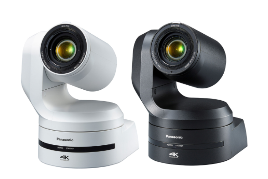
In a standard deployment, the AW-UE150 cameras and RP-150 controller are connected to the same local network, shown in the diagram below.
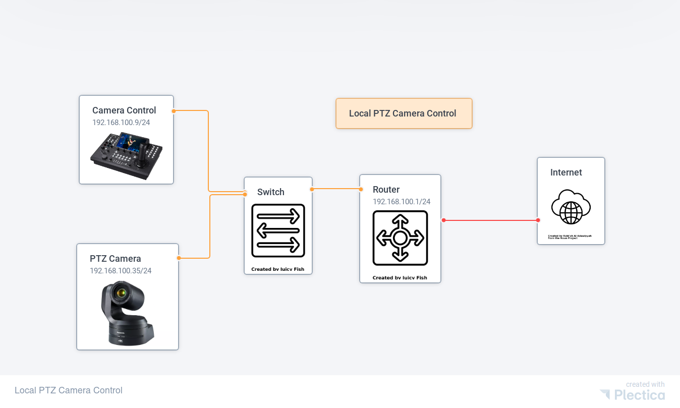
This local control network is how Panasonic designed these devices to work. The controller and camera communicate directly with each other over the IP-based network.
The rest of this guide will show you how to configure a network that can deliver remote control anywhere your cameras are deployed.
Remote Control Network Overview
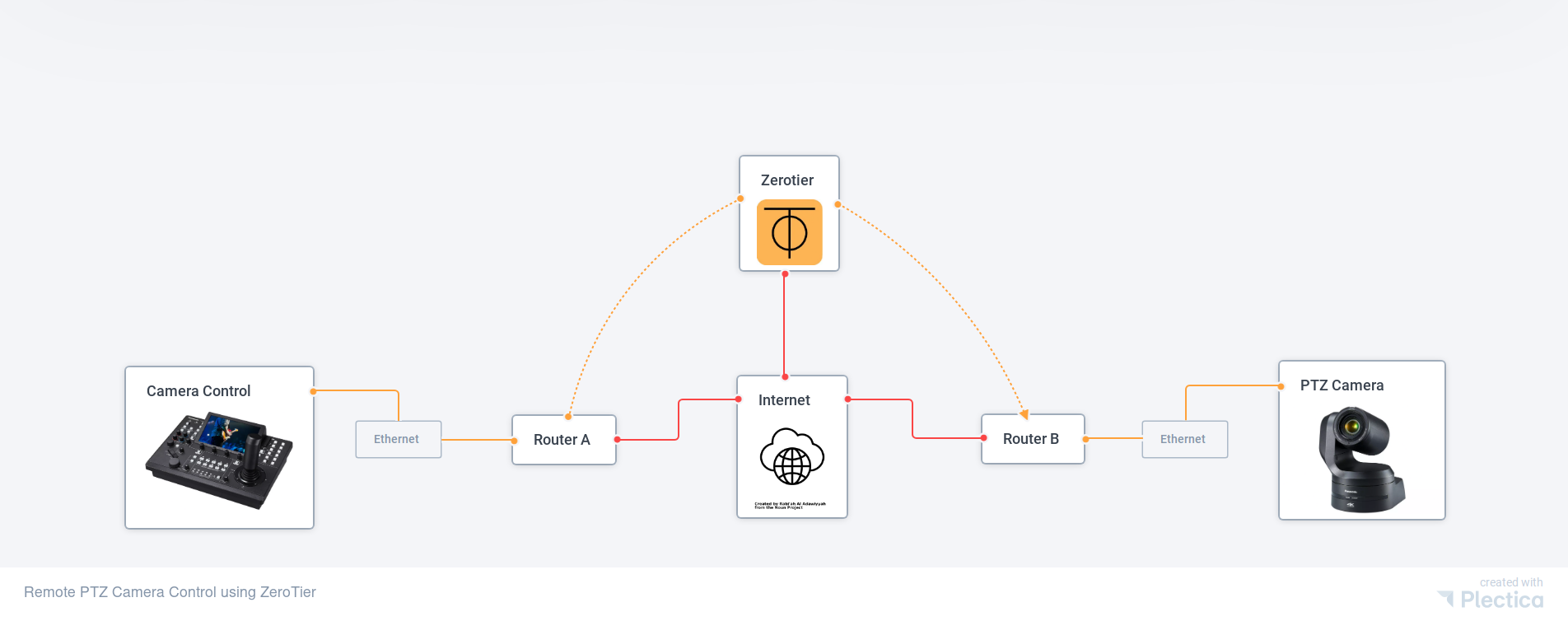
When the controller and camera are in two separate physical locations, connected to networks with independent connections to the Internet, they are normally unable to 'see' each other. These two networks are independent 'islands' that cannot communicate directly.
We will use ZeroTier tunnels to build a bridge between these two islands, as shown in the diagram below.
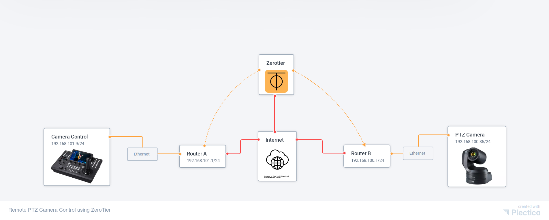
Network Configuration Overview
Camera Control
- Router: 192.168.101.1/24
- RP-150 Controller: 192.168.101.9/24
Remote PTZ
- Router: 192.168.100.1/24
- AW-UE150 4K PTZ camera: 192.168.100.35
Step-by-Step Configuration
Setting up ZeroTier
- Go to zerotier.com and Login or Sign Up for a new account. The free tier offers up to 25 nodes, the network we are building today only has two nodes.
- Once your account is created, click 'Create a Network' in the main dashboard.
- Click on the network you just created to enter the configuration page.
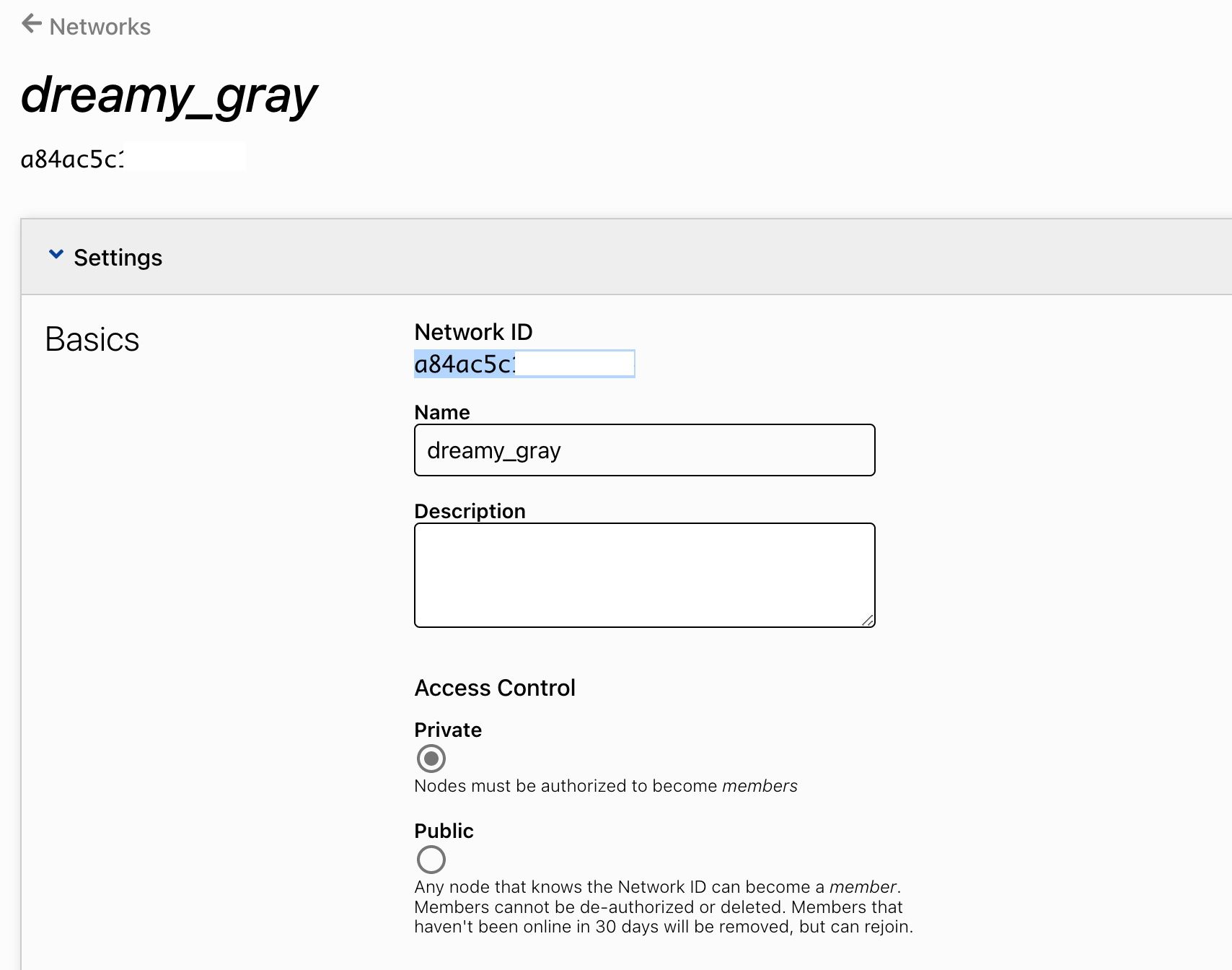
4. Make a note of the 16-character network ID. You will need this when we configure the ZeroTier client on the router. This is all you need to do on ZeroTier right now. We will return to this page later to make final changes.
Camera Control Network
Our next task is to configure the router; we are using GL.iNet Convexa routers. They provide a powerful hardware routing platform running OpenWRT, a widely supported open-source router firmware.
- Connect the GL.iNet router to the Internet via the WAN port (yellow). This connection could be direct to your cable modem or your router. The source of the internet connection isn't important because we're using ZeroTier to create a tunnel between each network. This delivers the flexibility required when moving the controller and cameras between different locations.
- Connect your laptop to the LAN port of the GL.iNet router, and power it up.
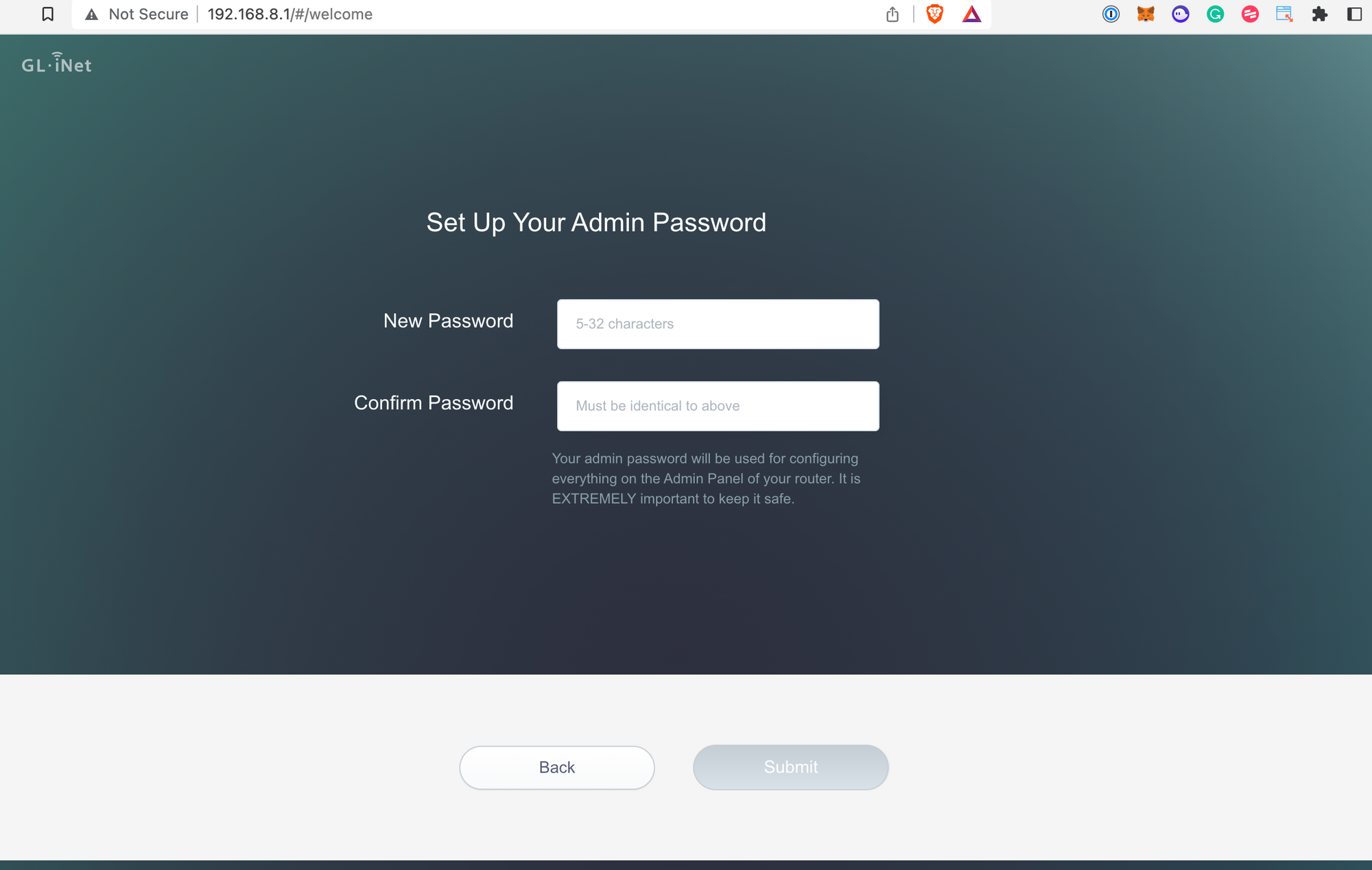
- Once the router is powered up, connect to the web interface using your browser by entering 192.168.8.1 into your browser's address bar.
- Set your preferred language, then add a password.
5. To configure the router's IP address, matching our design, select 'More Settings > LAN IP from the admin menu. Enter 192.168.101.1 as the LAN IP, the DHCP address range below will update automatically. Click Apply.
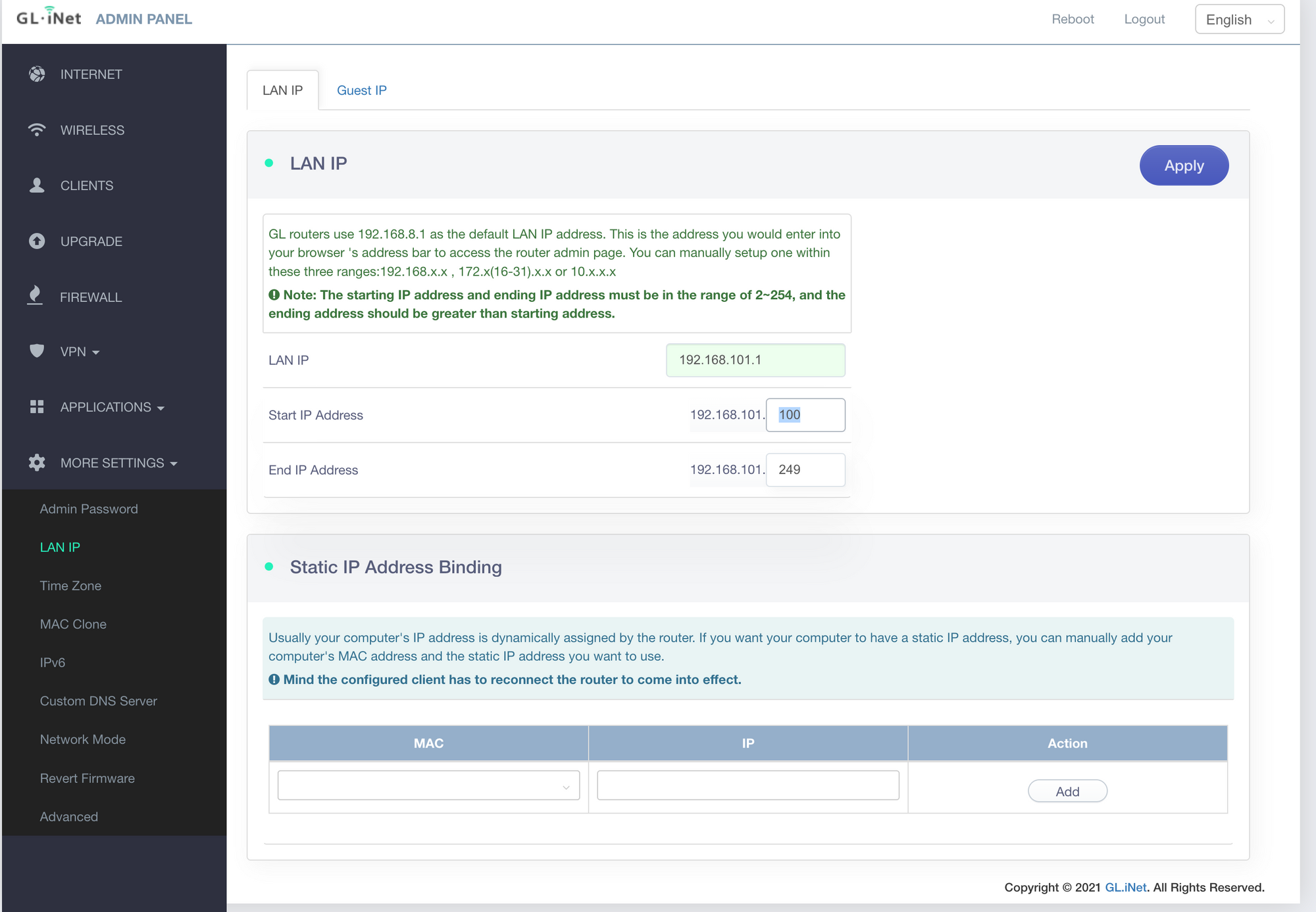
6. You should be redirected to the new address once the settings are applied. Otherwise, enter 192.168.101.1 in your browser's address bar and log in using the password you set previously.
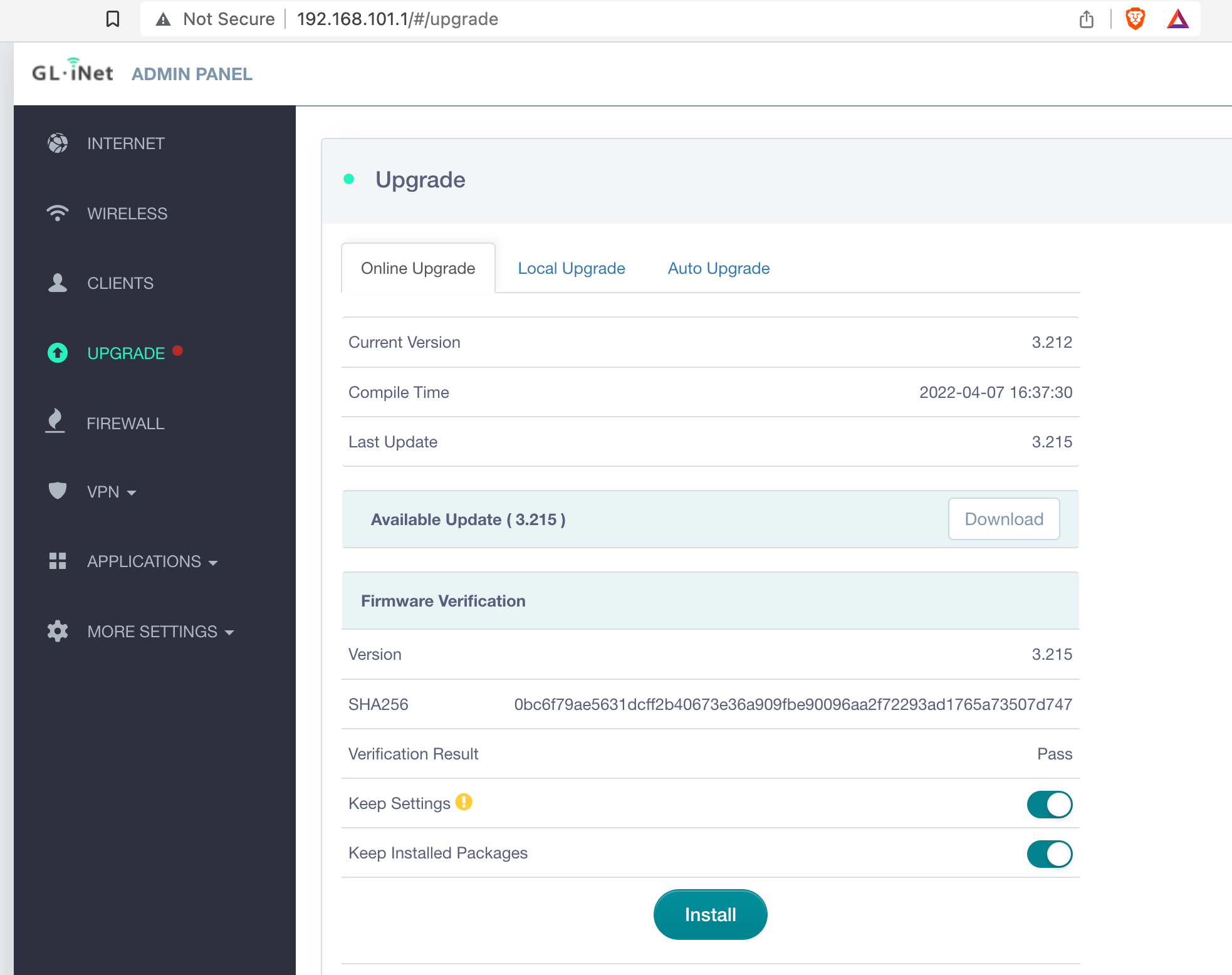
7. Select' Upgrade' from the admin menu to ensure the router is running the latest firmware. The router will check for new firmware and offer the option to Download, then install.
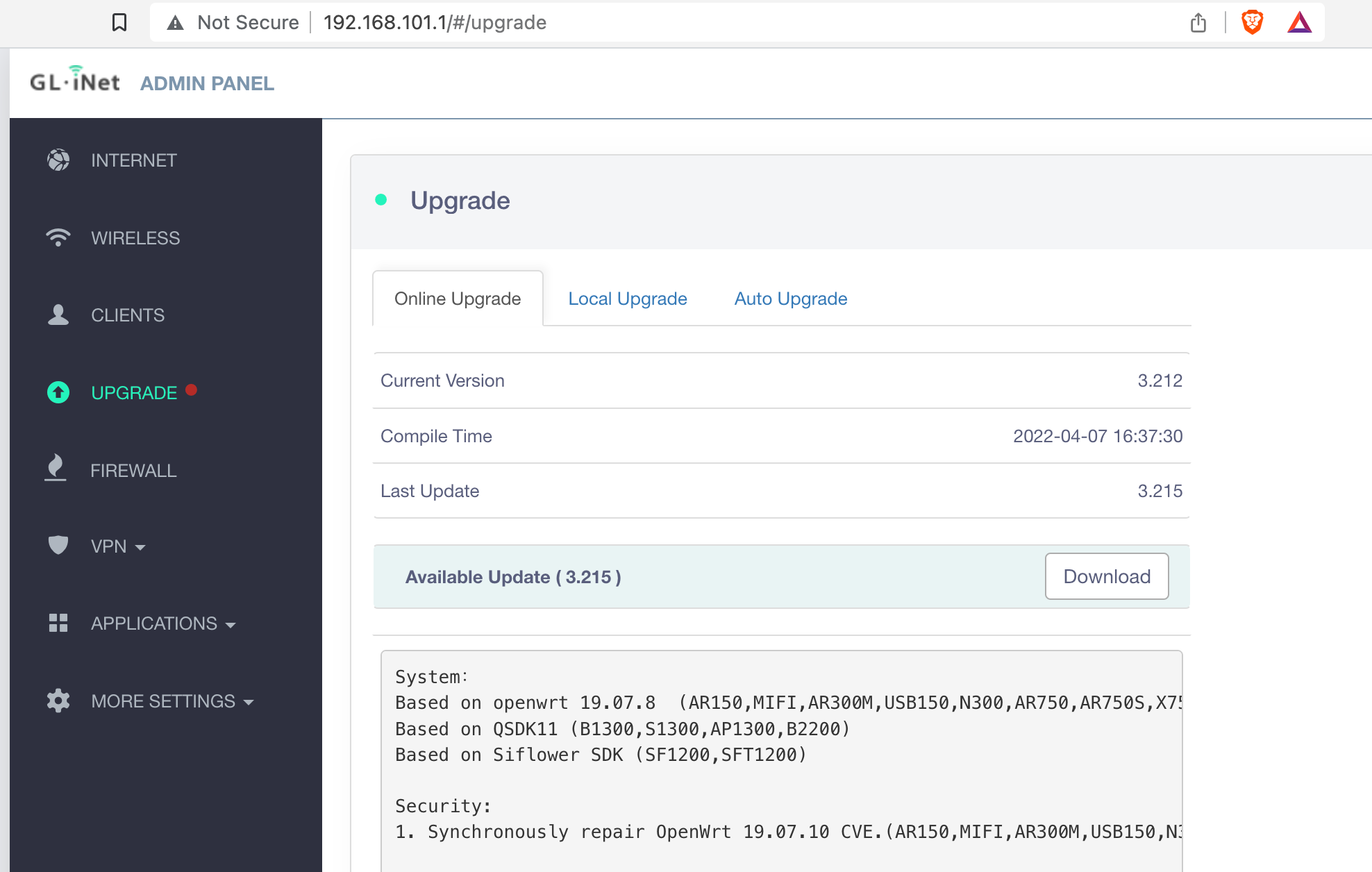
8. Select the options to keep settings and installed packages and click the 'Install' button. The automatic upgrade process will start, taking about 5 mins.
9. Once completed, you will be automatically redirected to the router's login page.
10. OpenWRT router functionality can be extended with installable Application packages or plug-ins. This is how we will add ZeroTier support to the router.
11. Select Applications > Plug-ins from the admin menu, and click 'Update' to ensure you have the latest available package list.
12. Once updated, enter 'zerotier' in the search box.

13. If two versions are listed as available, choose the latest. Version 1.8.4 in this case. You will receive a confirmation message once the package is installed.
14. Now is a good time to get a cup of tea, or your beverage of choice, as the next steps involve using the command line to configure ZeroTier.
15. Access the command line interface (CLI) via ssh. On windows, use Putty. I use iTerm2 on my Macbook.
16. Open your terminal client and start your ssh session by entering the command,
ssh root@192.168.101.1
You will be prompted to enter the router password set previously.
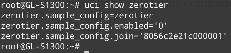
17. Confirm ZeroTier is installed by listing the sample config using this command;
uci show zerotier
The output will look like this;
18. We will continue to configure the connection to the ZeroTier network you created using the 'uci' commands below;
uci set zerotier.camcontroller=zerotier
uci add_list zerotier.camcontroller.join='yourZeroTierNetworkID'
uci set zerotier.camcontroller.enabled='1'
uci commit zerotier
Use the command uci show zerotier to confirm your settings are added to the configuration.
Restart the Zerotier service using the command;
/etc/init.d/zerotier restart
19. Return to your online ZeroTier admin dashboard at https://my.zerotier.com and click the network you created to enter the details page.
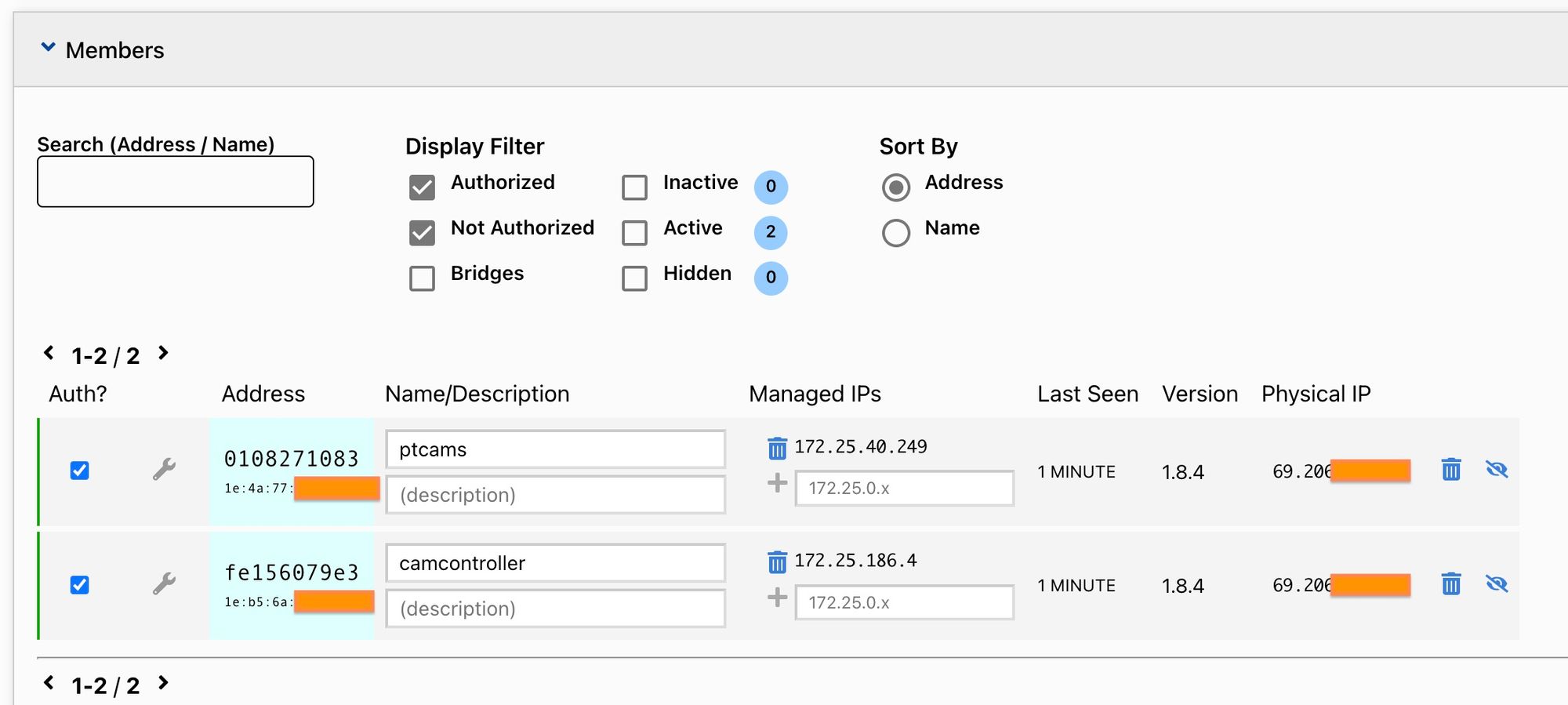
20. Scroll down to the 'Members' section, where you should see a new connection from your router.
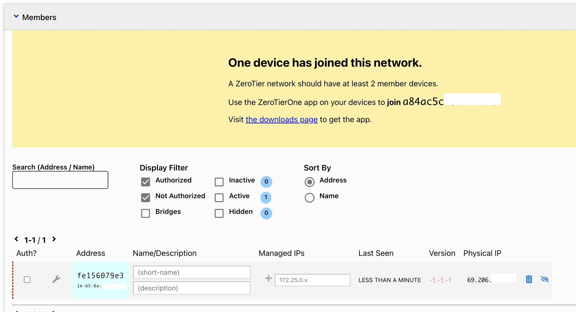
21. Click the checkbox in the 'Auth?' column to allow the router to connect to your ZeroTier network.
22. Click the spanner icon to open advanced settings for this device and click the checkbox 'Allow Ethernet Bridging'.
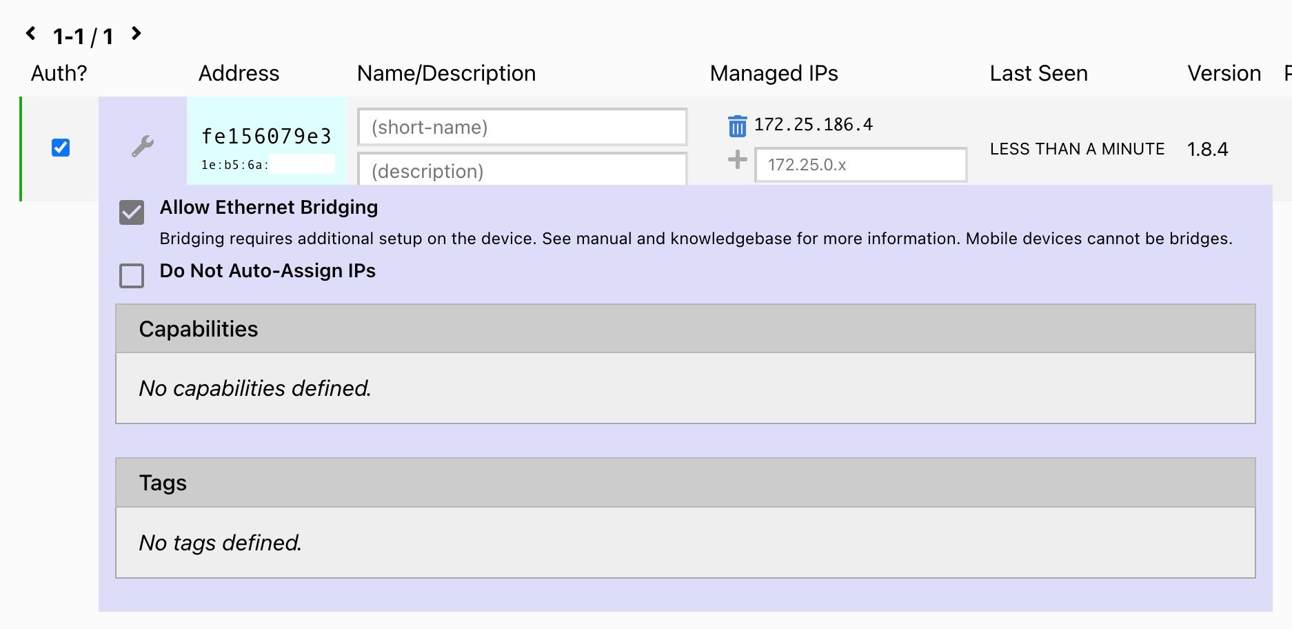
23. Note the 'Managed IP' of the device. In my case, 172.25.186.4
24. Scroll up to the 'Settings' section, and in the 'Advanced > Managed Routes' panel, enter
Destination 192.168.101.0/24
Via DeviceManagedIP you noted at Step 23.
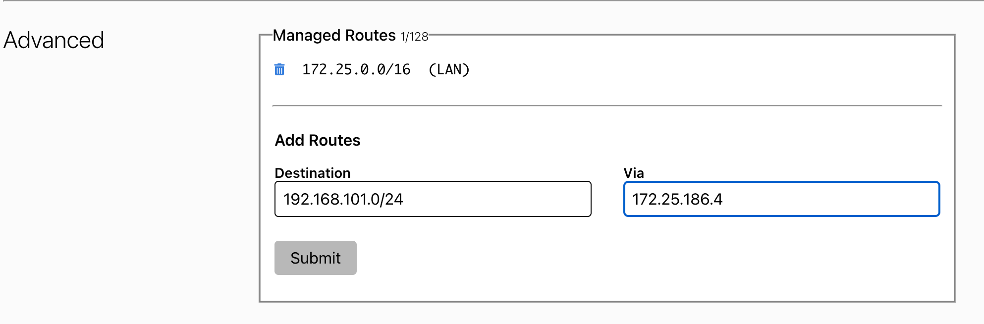
My configuration looks like the above.
Click Submit to save.
This tells the ZeroTier 'brain' that devices in your Controller network, 192.168.101.0/24 are reachable via the ZeroTier device IP address 172.125.186.4
25. This completes the ZeroTier configuration for now. We will return to the dashboard when we add the Camera router.
27. Returning to the command line interface of the router, let's confirm the Zerotier Interface is active by using the command;
ip a
This will output a list of the router's network interfaces and their IP addresses, which will look like this;
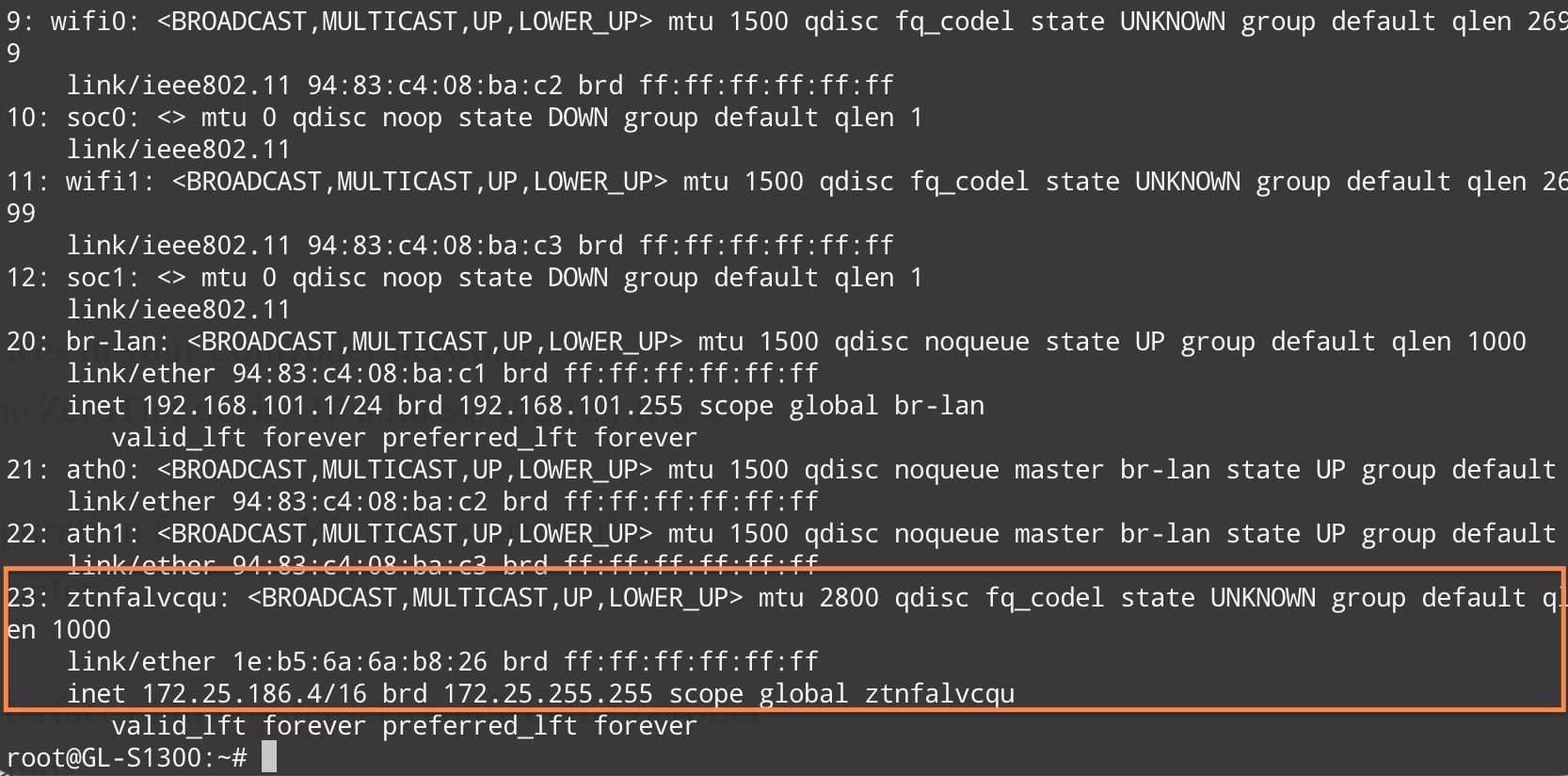
The ZeroTier interface can be identified easily as it starts with 'zt'. You can see it has the IP address listed from the ZeroTier dashboard, 172.25.186.4.
Congratulations! Your router is now connected to ZeroTier, great job.
28. We're nearly finished with the command line. Before exiting, we need to save the ZeroTier key so the router can automatically reconnect to ZeroTier after each reboot.
Use these commands to copy the ZeroTier key to your permanent configuration.
uci set zerotier.camcontroller.secret="$(cat /var/lib/zerotier-one/identity.secret)"
uci commit zerotier
Confirm the key has been saved in your config;
uci show zerotier
The output will now show an additional line
zerotier.camcontroller.secret="longStringOfAlphanumericCharacters"
If you want to test that this has been saved correctly, reboot your router using the command;
reboot
Wait a minute or so and confirm the ZeroTier connection is active via the ZeroTier dashboard and/or using the command ip a in the router's command line to view the interface list on the router.
29. Connect your Panasonic RP console to the LAN port of the router and either manually configure its IP address or set it to receive one automatically via DHCP.
This completes this section of the configuration. We will repeat these steps to configure the second router, which will be used for the PTZ camera(s).
Remote PTZ Network
- Steps 1 to 4 are the same as the Camera Control router configuration.
5. following the same process, configure the LAN IP of the router to 192.168.100.1.
6. Steps 6 to 15 are the same as the Camera Control router configuration.
16. Open your terminal client and start your ssh session by entering the command,
ssh root@192.168.101.1
You will be prompted to enter the router password set previously.
17. Confirm ZeroTier is installed by listing the sample config using this command;
uci show zerotier
The output will look like this;
18. We will continue to configure the connection to the ZeroTier network you created using the 'uci' commands below;
uci set zerotier.ptzcams=zerotier
uci add_list zerotier.ptzcams.join='yourZeroTierNetworkID'
uci set zerotier.camcontroller.enabled='1'
uci commit zerotier
Use the command uci show zerotier to confirm your settings are added to the configuration.
Restart the Zerotier service using the command;
/etc/init.d/zerotier restart
19. Steps 19 to 23 are the same as the Camera Control router configuration.
24. Scroll up to the 'Settings' section, and in the 'Advanced > Managed Routes' panel, enter
Destination 192.168.100.0/24
Via DeviceManagedIP you noted in Step 23.
25. Steps 25 to 28 are the same as the Camera Control router configuration.
29. Connect your Panasonic AW PTZ camera to the router's LAN port and either manually configure its IP address or set it to receive one automatically via DHCP.
30. Your Zerotier dashboard should now show both routers connected to the service.
Cool huh? We're very close to Getting the controller and camera 'talking' to each other via ZeroTier. All that remains is some firewall configuration on each router to allow traffic to pass across the ZeroTier link.
Final Configuration and Testing
The configuration steps are the same for each router.
- Log into the router's web UI and select 'More Settings > Advanced'. You may be prompted to install the advanced 'Luci' web UI.
- Click the link to access the Luci web ui, entering root/yourPassword to access.
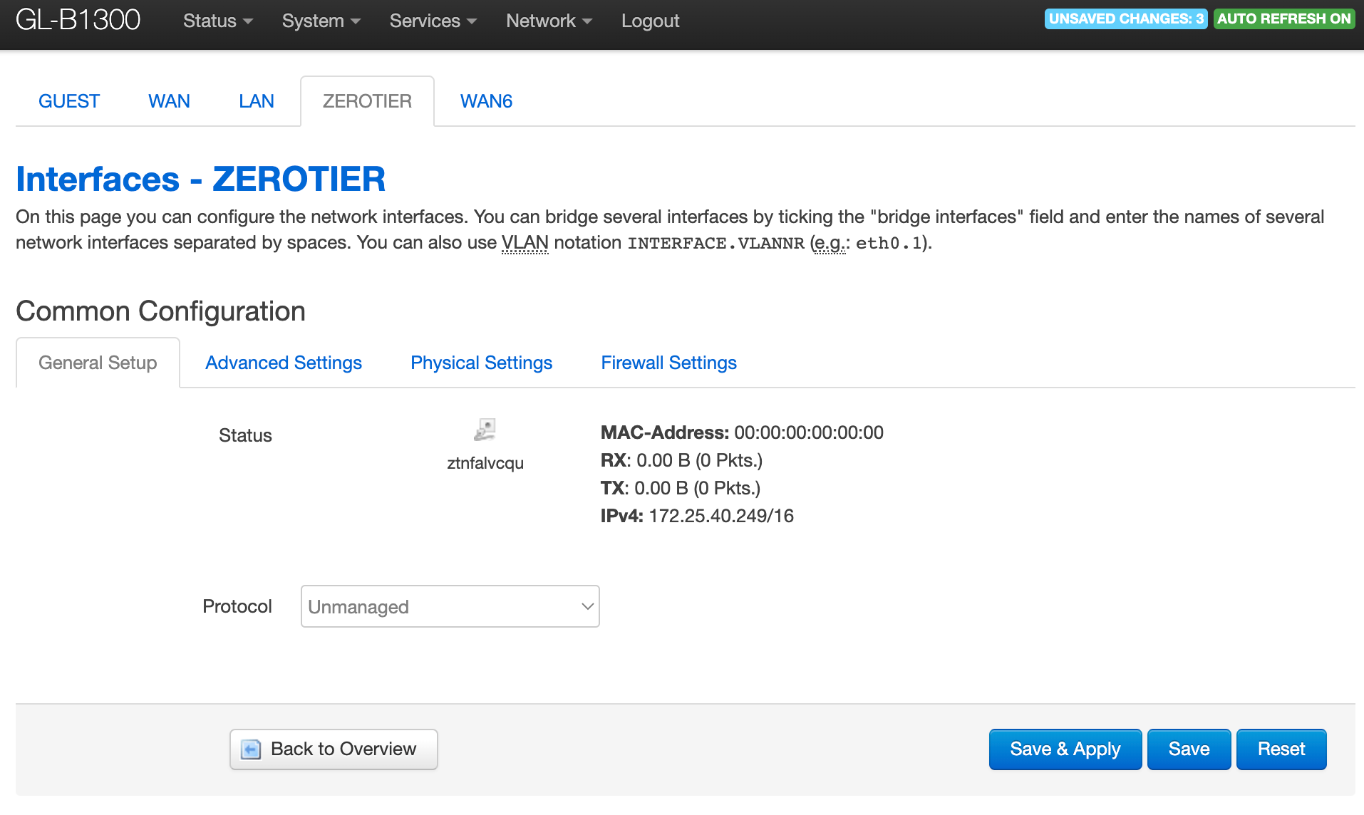
- Select 'Network > Interfaces' and click the button to 'Add new Interface'.
- Name the interface 'zerotier', set the Protocol of the new interface to 'Unmanaged', and select the ZeroTier interface from the list below. It will be listed as an Ethernet Adapter starting with 'zt'.
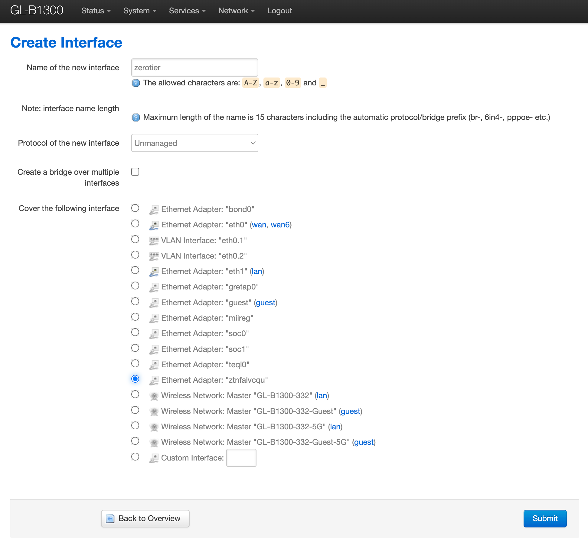
Click Submit.
On the next page, confirm your settings and click 'Save & Apply'
5. Once complete, you should be returned to the 'Network > Interfaces' page. From the menu, select 'Network > Firewall', and in the 'Zones' section, click the 'Add' button.
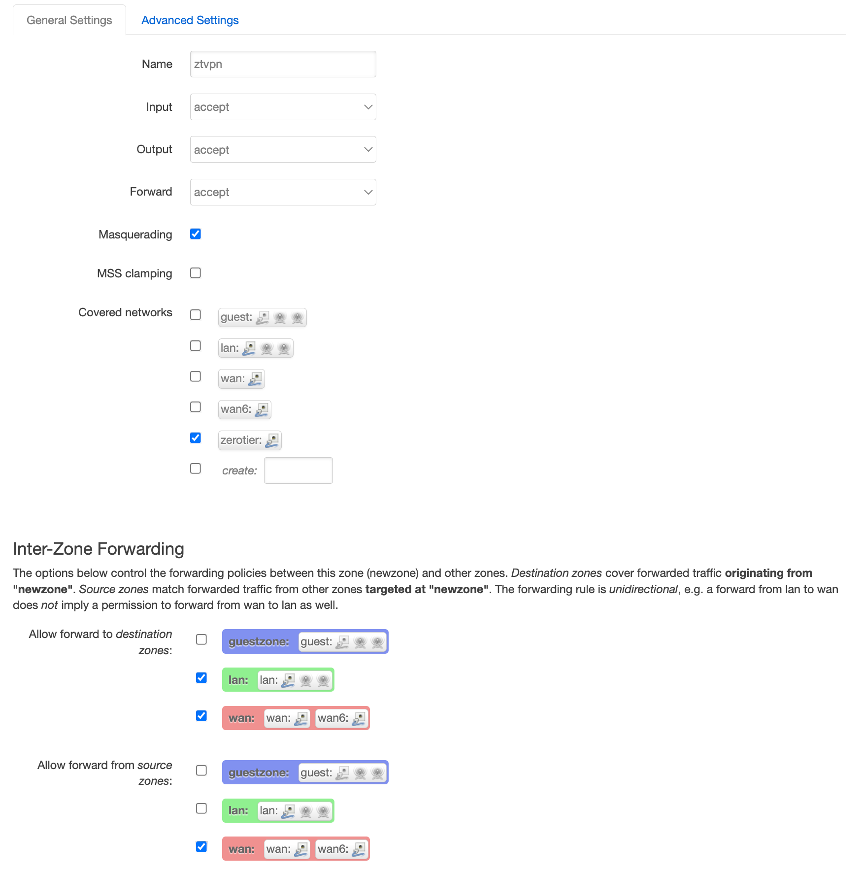
6. Configure the new zone as follows;
- Name: ztvpn
- Input: Accept
- Output: Accept
- Forward: Accept
- Masquerading: Checked
- Covered Networks: zerotier
- Allow forward to destination zones: Check LAN, WAN
- Allow forward from zones: Check LAN.
It should look like the screenshot below.
Click 'Save & Apply'
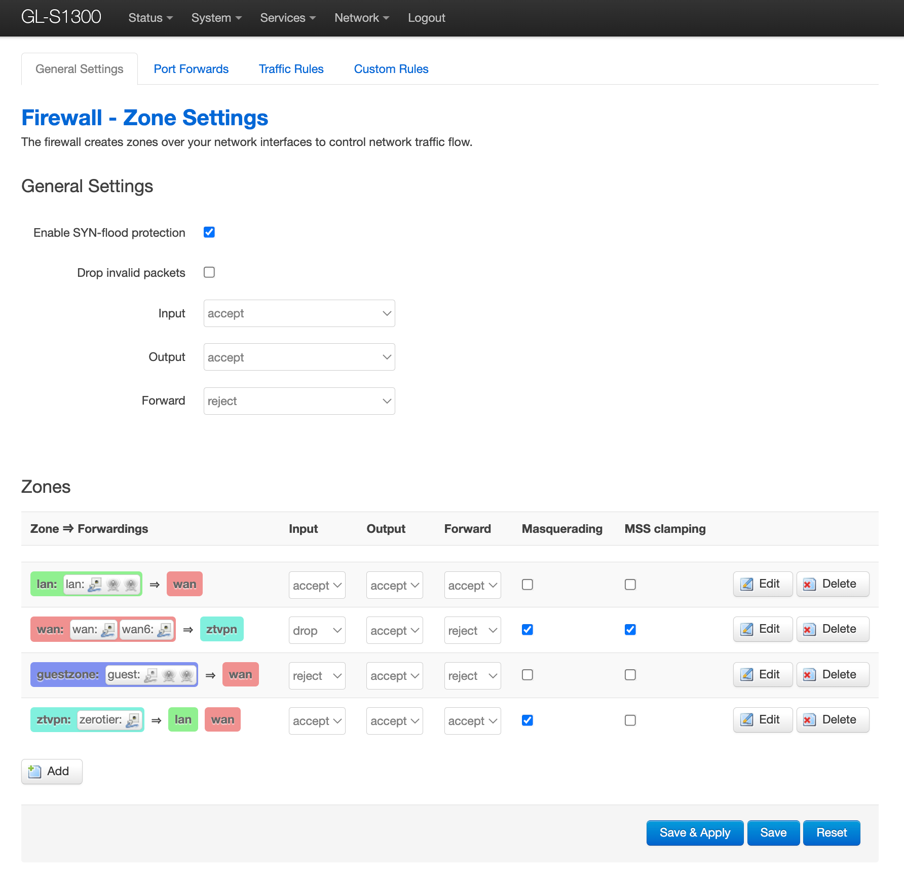
Your Firewall page should now look like this;
7. Once this is completed on both routers, we are ready to test connectivity between the two networks.
8. Connect your laptop to the Ethernet of the Camera Controller router
9. Open your terminal and attempt to ping the remote router LAN interface;
ping 192.168.100.1
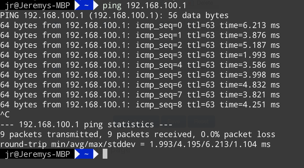
10. Next, ping the IP address of the camera, in my case, 192.168.100.35.
ping 192.168.100.35
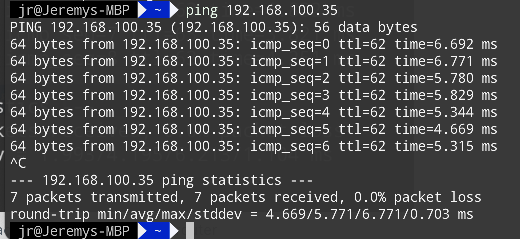
SUCCESS!! 🥳
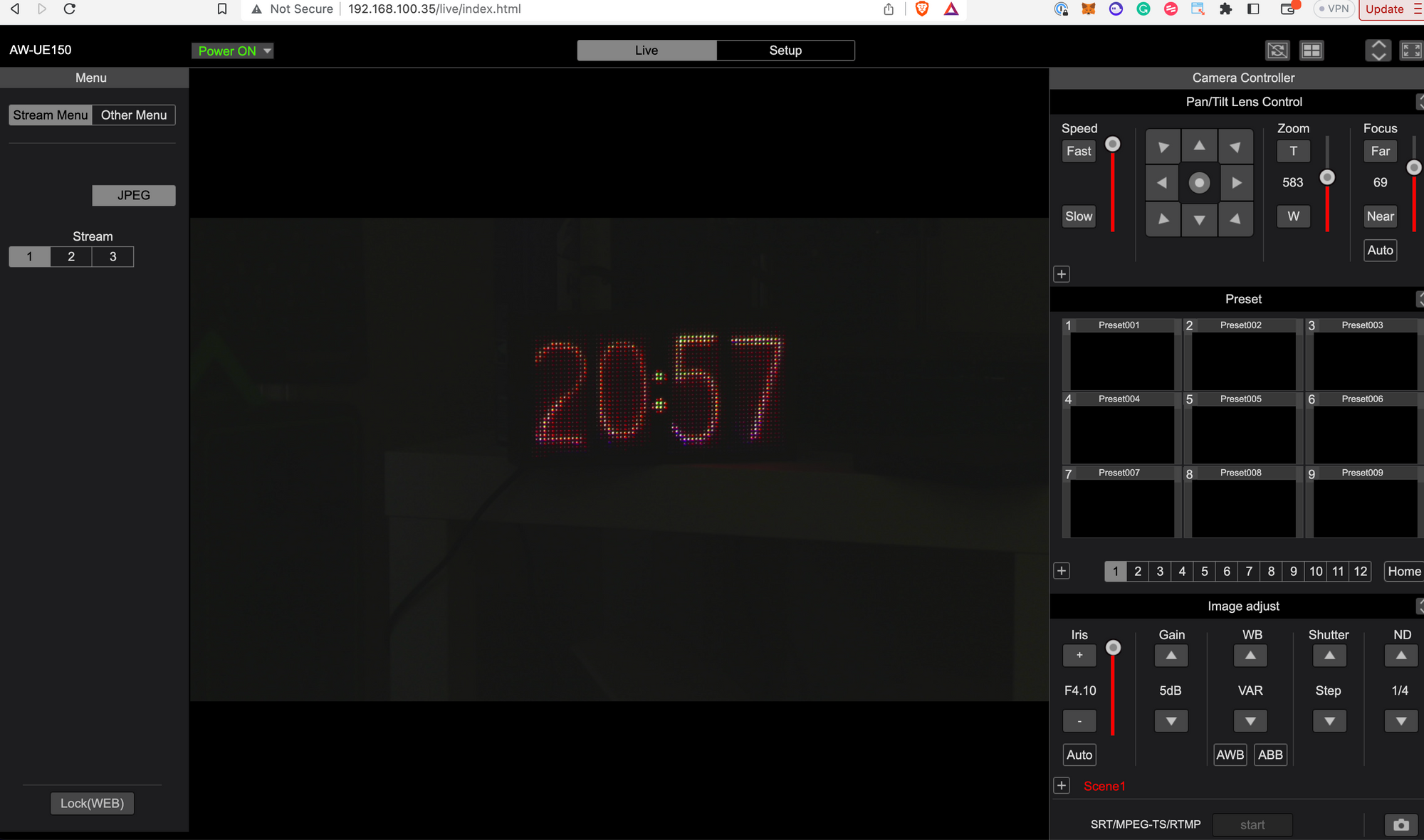
11. Set the camera's IP address in your RP controller, and you'll be all set to remotely control your camera(s).
Hiram and I will be continuing to refine and test this configuration. Keep an eye out for future posts as we test SRT streaming over the link and refine the performance of the connection.
I hope you found this guide useful please consider subscribing to WaveRiders or sharing it on your socials. If you have questions or comments, contact me via Mastodon or LinkedIn or email jr at waveriderswireless dot com.